SWaT tutorial
This tutorial shows how to use MiniCPS to simulate a subprocess of a Water Treatment testbed. In particular, we demonstrate basic controls through simulated PLCs, the network traffic, and simple physical layer simulation. We now provide:
- A list of the pre-requisites to run the tutorial
- A brief system overview
- Step-by-step instructions to run and modify the simulation
Prerequisites
This tutorial assumes that the reader has a basic understanding of python
2.x, has familiarly with Linux OS, bash, Mininet
and has a basic understanding of networking tools such
as: wireshark, ifconfig and nmap.
This tutorial will use the following conventions for command syntax:
command- is typed inside a terminal (running
bash) mininet> command- is typed inside mininet CLI
C-d- it means to press and hold
Ctrland then pressd.
Before continuing please read the API doc.
System Overview
This tutorial is based on the Secure Water Treatment (SWaT) testbed, which is used by Singapore University of Technology and Design (SUTD)’s researcher and students in the context of Cyber-Physical systems security research.
SWaT’s subprocess are the followings:
- P1: Supply and Storage
- Collect the raw water from the source
- P2: Pre-treatment
- Chemically pre-treat the raw water
- P3: UltraFiltration (UF) and Backwash
- Purify water and periodically clean the backwash filter
- P4: De-Chlorination
- Chemically and/or physically remove excess Chlorine from water
- P5: Reverse Osmosis (RO)
- Purify water, discard RO reject water
- P6: Permeate transfer, cleaning and back-wash
- Storage of permeate (purified) water
Supply and Storage control
The simulation focuses on the first subprocess of the SWaT testbed.
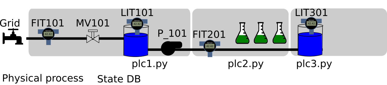
As you can see from the figure, during normal operating conditions the water flows into a Raw water tank (T101) passing through an open motorized valve MV101. A flow level sensor FIT101 monitors the flow rate providing a measure in m^3/h. The tank has a water level indicator LIT101 providing a measure in mm. A pump P101 [1] is able to move the water to the next stage. In our simulation we assume that the pump is either on or off and that its flow rate is constant and can instantly change value.
The whole subprocess is controlled by three PLCs (Programmable Logic Controllers). PLC1 takes the final decisions with the help of PLC2 and PLC3. The following is a schematic view of subprocess’s control strategy:
- PLC1 will first:
- Read LIT101
- Compare LIT101 with well defined thresholds
- Take a decision (e.g.: open P101 or close MV101)
- Update its status
Then PLC1 has to communicate (using EtherNet/IP) with PLC2 and PLC3 that are monitoring subprocess2 and subprocess3.
- PLC1 will then:
- Ask to PLC2 FIT201’s value
- Compare FIT201 with well defined thresholds
- Take a decision
- Update its status
- Ask to PLC3 LIT301’s value
- Compare LIT301 with well defined thresholds
- Take a decision
- Update its status
Notice that asking to a PLC is different from reading from a sensor, indeed our simulation separate the two cases using different functions.
| [1] | The real system uses two redundant pumps, one is working and the other is in stand-by mode. |
MiniCPS simulation
Topology
To initialize the simulation environment open up a terminal, navigate into the
root minicps directory, (the one containing a Makefile) and type:
make swat-s1-init
To start the simulation, from the same directory type:
make swat-s1
Now you should see the mininet CLI:
mininet>
Feel free to explore the network topology using mininet’s built-in
commands such as: nodes, dump, net, links etc.
At this time you should be able to answer questions such as:
- What is the IP address of PLC1?
- What are the (virtual) network interfaces?
- What is the network topology?
If you want to open a shell for a specific device, let’s say plc1
type:
mininet> xterm plc1
Now you can type any bash command from plc1 node, such that ping or
ifconfig.
At this time you should be able to answer questions such as:
- Are there web servers or ftp servers running on some host ?
- Is the file system shared ?
Another convenient way to run bash commands is directly from the mininet prompt, for example type:
mininet> s1 wireshark
You can exit mininet by pressing C-d or typing:
mininet> exit
You can optionally clean the OS environment typing:
make clean-simulation
Customization
Open a terminal and cd examples/swat-s1/. The files contained in this folder
can be used as a template to implement your Cyber-Physical System simulation.
For example you can copy it in your home folder and start designing your CPS
simulation.
For the rest of the section we will use our SWaT subprocess simulation example to show how to design, run and configure MiniCPS. Let’s start describing the various files used for the simulation.
The init.py script can be run once to generate the sqlite database containing
the state information.
The topo.py script contains the mininet SwatTopo(Topo) subclass used to set the
CPS topology and network parameters (e.g., IP, MAC, netmasks).
The run.py script contains the SwatS1CPS(MiniCPS) class that you can
use to customize your simulation. In this example the user has to manually run the
PLC logic scripts and physical process script, for example opening four xterm from the
mininet> prompt and launch the scripts.
You can start every script automatically uncommenting the following lines:
        plc2.cmd(sys.executable + ' plc2.py &')
        plc3.cmd(sys.executable + ' plc3.py &')
        plc1.cmd(sys.executable + ' plc1.py &')
        s1.cmd(sys.executable + ' physical_process.py &')
In this example it is required to start plc2.py and plc3.py
before plc1.py because the latter will start requesting Ethernet/IP
tags from the formers to drive the system.
The utils.py module contains the shared constants and the configuration
dictionaries for each MIniCPS Device subclass. Let’s take as an illustrative
example plc1 configuration dictionaries:
PLC1_ADDR = IP['plc1']
PLC1_TAGS = (
    ('FIT101', 1, 'REAL'),
    ('MV101', 1, 'INT'),
    ('LIT101', 1, 'REAL'),
    ('P101', 1, 'INT'),
    # interlocks does NOT go to the statedb
    ('FIT201', 1, 'REAL'),
    ('MV201', 1, 'INT'),
    ('LIT301', 1, 'REAL'),
)
PLC1_SERVER = {
    'address': PLC1_ADDR,
    'tags': PLC1_TAGS
}
PLC1_PROTOCOL = {
    'name': 'enip',
    'mode': 1,
    'server': PLC1_SERVER
}
The PLC1_PROTOCOL dictionary
allows MiniCPS to use the correct network configuration settings for the
send and receive methods, in this case for plc1
MiniCPS will initialize a cpppo Ethernet/IP servers with the specified
tags.
It is important to understand the mode encoding, mode is expected to be
a non-negative integer and it will set networking mode of the associated
Device.
Use a 1 if you want a device that both is serving enip tags and
it is able to query an enip server, e.g., a PLC device.
Use a 0 if you want a device has only enip client capabilities,
e.g., an HMI device.
In case you want to simulate a Device that has no network capabilites you can
set the protocol dict to None, e.g., a Tank device.
PATH = 'swat_s1_db.sqlite'
NAME = 'swat_s1'

STATE = {
    'name': NAME,
    'path': PATH
}
The STATE dictionary is shared among devices and
allows MiniCPS to use the correct physical layer API for the set and
get methods.
The simulation presents both physical and network interaction and the nice thing about MiniCPS is that any device can use the same addressing strategy to interact with the state and to request values through the network. This example uses the following constants tuples as addresses:
MV101 = ('MV101', 1)
P101 = ('P101', 1)
LIT101 = ('LIT101', 1)
LIT301 = ('LIT301', 3)
FIT101 = ('FIT101', 1)
FIT201 = ('FIT201', 2)
We are using two fields, the first is a str indicating the name of the
tag and the second is an int indicating the plc number. For example:
- plc2 will store an addressable real enip tag using
FIT201_2 = ('FIT201', 2) - plc1 will store in its enip server an addressable real enip tag using
FIT201_1 = ('FIT201', 1)
If you want to change the initial values of the simulation open
physical_process.py and look at:
        self.set(MV101, 1)
        self.set(P101, 0)
        self.level = self.set(LIT101, 0.800)
If you want to change any of the plcs logics take a look at plc1.py,
plc2.py and plc3.py and remember to set the relevant values in the
utils.py module.
If you manually run the logic script you can plug-and-play them in any fashion, e.g., you can test the same plc logics in a scenario where a tank is supposed to overflow and then stop the physical_process script and run another one where the tank is supposed to underflow, without stopping the plcs scripts.
The log/ directory is used to store log information about the simulation.
You can clean the simulation environment from minicps root directory using:
make clean-simulation